Home » PANDA » PandaRoot » Bugs, Fixes, Releases » Geometry Problems
| Geometry Problems [message #19230] |
Tue, 19 April 2016 14:47  |
 Stefan Pflueger
Messages: 99
Registered: February 2012
|
continuous participant |
From: *kph.uni-mainz.de
|
|
Hello everybody,
I wanted to inform you about a problem we have been dealing with the last week concerning our lumi detector geometry. Since this can also affect many other detector subsystems I wanted to share this with you. After an update of the fairroot (FairRoot-v-15.03) and external packages (mar15), we discovered that our 2 dimensional angular acceptance all of a sudden showed almond like shaped inefficiencies on the edges of our modules.
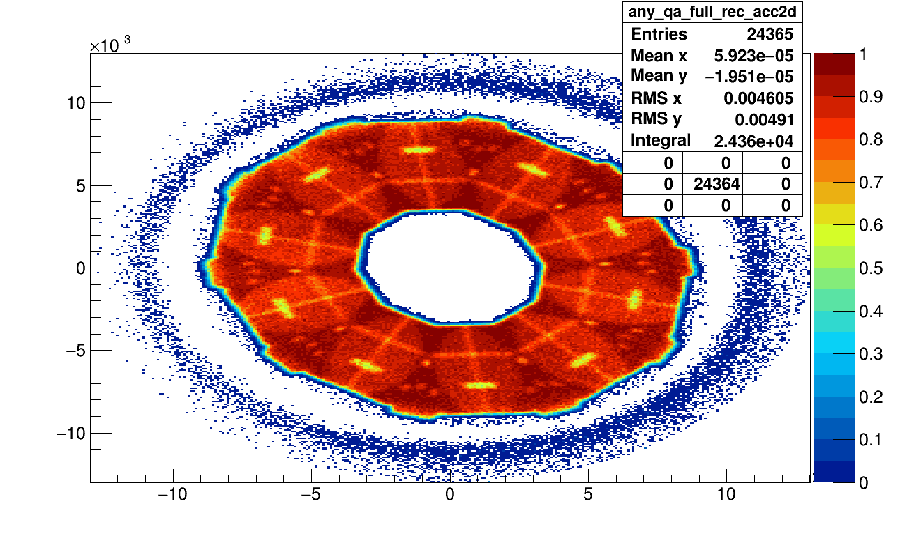
We analyzed the situation and came to the conclusion that this effect arises from the geometry not being constructed or simulated as we wanted.
We have 10 modules aligned around the beampipe in circle. Each module consists of a diamond support and cooling structure having glued on 5 MuPix sensors on its front and 5 more on this back face. 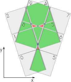 The problem was that the diamond structure was constructed from a circle (or complete tube segment) and then being cut to the appropriate dimensions via a CompositeShape. The problem was that the diamond structure was constructed from a circle (or complete tube segment) and then being cut to the appropriate dimensions via a CompositeShape.
876	        // ****************************** cvd cooling support discs ************************
877	        // the cvd disc shape
878	        TGeoTube* shape_cvd_disc = new TGeoTube("shape_cvd_disc", 0.,
879	                        cvd_disc_rad, cvd_disc_thick_half);
880	        // The inner beam pipe defines the inner acceptance region for the cvd cut_out
881	        TGeoTube* shape_cvd_cutout_inner = new TGeoTube("shape_cvd_cutout_inner",
882	                        0., inner_rad, 1.);
883	        // finally cvd discs will be cut at the left and right down to 36 degree in phi
884	        // for that we subtract tube segments
885	        TGeoTubeSeg* shape_cvd_disc_cut_side = new TGeoTubeSeg(
886	                        "shape_cvd_disc_cut_side", 0., outer_rad, 1.,
887	                        +delta_phi / 2. / pi * 180.,
888	                        -delta_phi / 2. / pi * 180.);
889	        // before: cvd disc was moved to the displaced position around the z axis
890	        // now: segments for the cut are moved off centered and cvd disc remains in the center
891	        TGeoRotation* cvd_rotation = new TGeoRotation("cvd_rotation", 0, 0, 0);
892	        TGeoTranslation* cvd_translation = new TGeoTranslation("cvd_translation",
893	                        -cvd_disc_dist, 0, 0);
894	        TGeoCombiTrans* cvd_combtrans = new TGeoCombiTrans(*cvd_translation,
895	                        *cvd_rotation);
896	        cvd_combtrans->SetName("cvd_combtrans");
897	        cvd_combtrans->RegisterYourself();
898	        TGeoCompositeShape
899	        *shape_cvd_support =
900	                        new TGeoCompositeShape(
901	                                        "shape_cvd_support",
902	                                        "(shape_cvd_disc-shape_cvd_cutout_inner:cvd_combtrans-shape_cvd_disc_cut_side:cvd_combtrans)");
903
904	        TGeoVolume* lmd_vol_cvd_disc = new TGeoVolume("lmd_vol_cvd_disc",
905	                        shape_cvd_support, fgGeoMan->GetMedium("HYPdiamond"));
906	        lmd_vol_cvd_disc->SetLineColor(9);
The problem was that when we visually checked the geometry, everything seemed just fine. However in the simulation, the diamond was not cut off but the full circular shaped remained! Hence we observed a twice as high material budget on the edges of our modules that created this inefficiency in the acceptance.
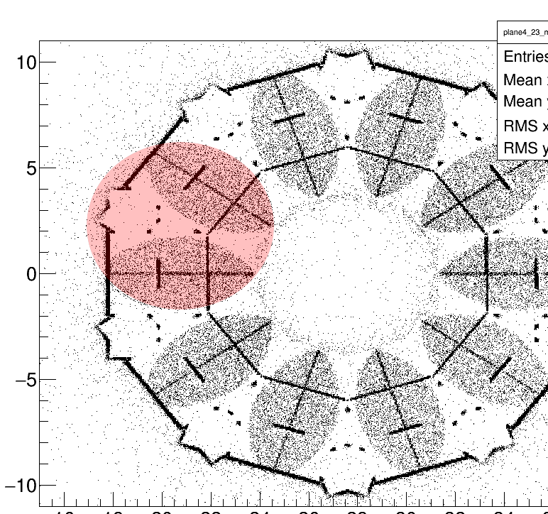
The red circle drawn into this picture would show where the diamond wafer would be sitting and its shows that it perfectly aligns with this almond like shape in the acceptance.
So simply changing this diamond shape to a tube segment with the correct phi and radii from the beginning on, prevented this overlap from appearing and the acceptance looked fine again.
// the cvd disc shape
886	        double gap_between_disc_and_support_structure(0.025); // 250 mu gap
887	        TGeoTubeSeg* shape_cvd_disc = new TGeoTubeSeg("shape_cvd_disc", inner_rad,
888	                        lmd_cool_sup_inner_rad - gap_between_disc_and_support_structure,
889	                        cvd_disc_thick_half, -delta_phi / 2. / pi * 180.,
890	                        +delta_phi / 2. / pi * 180.);
891
892	        TGeoRotation* cvd_rotation = new TGeoRotation("cvd_rotation", 0, 0, 0);
893	        TGeoTranslation* cvd_translation = new TGeoTranslation("cvd_translation",
894	                        -cvd_disc_dist, 0, 0);
895	        TGeoCombiTrans* cvd_combtrans = new TGeoCombiTrans(*cvd_translation,
896	                        *cvd_rotation);
897	        cvd_combtrans->SetName("cvd_combtrans");
898	        cvd_combtrans->RegisterYourself();
899
900	        //this next line is pretty stupid but it made the work for the better geometry minimal
901	        //otherwise I would have to do some deeper digging and reworking...
902	        TGeoCompositeShape *shape_cvd_support = new TGeoCompositeShape(
903	                        "shape_cvd_support",
904	                        "(shape_cvd_disc:cvd_combtrans+shape_cvd_disc:cvd_combtrans)");
905
906	        TGeoVolume* lmd_vol_cvd_disc = new TGeoVolume("lmd_vol_cvd_disc",
907	                        shape_cvd_support, fgGeoMan->GetMedium("HYPdiamond"));
908	        lmd_vol_cvd_disc->SetLineColor(9);

Either we are not using the composite shapes correctly in our code or ROOT seems to have a bug there.... Did anyone ever experience similar problems. I guess we were also lucky seeing this after all, as the material budget has to be just enough to actually slow down the particles enough so they are not seen in the last layers of the tracking detector anymore.
Best regards,
Stefan
-
 Attachment: acc2d.png
(Size: 72.87KB, Downloaded 505 times)
-
Attachment: circle.png
(Size: 77.86KB, Downloaded 467 times)
-
Attachment: sensor-overlap-new.png
(Size: 27.70KB, Downloaded 472 times)
-
Attachment: acc2d.png
(Size: 67.31KB, Downloaded 409 times)
[Updated on: Tue, 19 April 2016 14:53] Report message to a moderator |
|
|
|
Current Time: Fri Apr 19 18:36:25 CEST 2024
Total time taken to generate the page: 0.01371 seconds
|
 GSI Forum