Home » NUSTAR » NUSTAR PRESPEC » Position calculations on start/stop scintillators
|
|
| Re: Position calculations on start/stop scintillators [message #18126 is a reply to message #18119] |
Thu, 09 April 2015 15:16   |
 miree
miree
Messages: 71
Registered: June 2014
|
continuous participant |
From: *ikp.physik.tu-darmstadt.de
|
|
Hi,
I guess it is not optimally calibrated. The ToF position determination is very dependent on a good calibration of all PMTs.
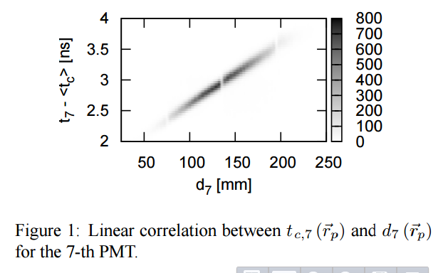
By PMT calibration I mean position correction, i.e. the dependence of delta_t(delta_x), where delta_t is the time delay between particle hit and PMT signal, and delta_x is the distance between the particle hit position and the PMT position.
The calibration goes like this: Plotting delta_t over delta_x and determine the slope and offset of the resulting structure
How this structure should look like a straight line (see Figure 1 of this GSI report: http://repository.gsi.de/record/52088/files/PHN-ENNA-EXP-55.pdf)
The offset (intersection of the line with y-axis) and slope (of the line) for each PMT have to be copied into the calibration file for the ToF processor "ToFStart.cal"
This calibration might change between experiments (mainly because of differences in PMT voltages, I guess).
In the prespec analysis script, these corellation plots are created in this section:
########################################################################
# Time of flight start detector
########################################################################
processor Lycca/ToFStart/Preproc   UTILS.MhTdcPreprocessor
	input[0:15]     <-   LyccaTargetTofCrate.mhtdc0[0:15]
	input[16:31]    <-   LyccaTargetTofCrate.mhtdc1[16:31]
	# ...
end
processor Lycca/ToFStart/Membrane         LYCCA.CircularMembraneScintillator
	pmt_time[0:31]   <-    Lycca/ToFStart/Preproc.output[0:31]
	x_hit            <-    Frs/S4tracking.xs[5]
	y_hit            <-    Frs/S4tracking.ys[5]
        #....
end
# create the delata_t vs. distance corellation plots for all 32 PMTs
# Membrane.dist[i] is the distance of PMT_i to the particle impact point
# Membrane.T_Tp[i] is the time of PMT_i minus the estimated time of particle impact
for $i in [0:31]
	processor Lycca/ToFStart/Diagnostics/Tdist0$i     UTILS.Pair
		first   <-   Lycca/ToFStart/Membrane.dist[$i]
		second  <-   Lycca/ToFStart/Membrane.T_Tp[$i]
		display first:second 256,0,300:512,-35,55       in   TofStart_Tdist_corrlation
	end
end
Note that the corellation plot depends on the calibration parameters, the complete process is iterative:
1)start with initial values for offsets and slopes in the calibration file: 0 and 0.01 are good starting values
2)determine offsets and slopes from the corellation plot
3)go to 1)
(2 to 3 iterations are usually enough)
Michael
|
|
|
|
|
|
| Re: Position calculations on start/stop scintillators [message #18195 is a reply to message #18119] |
Fri, 08 May 2015 11:23 |
miree
Messages: 71
Registered: June 2014
|
continuous participant |
From: *ikp.physik.tu-darmstadt.de
|
|
Ideally, the 2D histogram should look like the one in the GSI report in my earlier post.
To get these nice lined, every PMT has to work fine.
In your case something is wrong, but it is hard to tell from this single picture.
Whenever I didn't get the good looking lines, I tried to exclude signals from some PMTs (by trial and error), sometimes a single PMT can disturb all histograms.
If this doesn't help one can also start with a small number of PMTs (2 or 3) for which the correlation plots look good, and successively add more. Each time one hast to check if the histograms still look good. If they don't look good after adding the PMT #n, you know that PMT #n is not good and skip it.
Another (possibly simpler) way is to determine the correlations not using the signals from the LYCCA.CircularMembraneScintillator outputs, but by subtracting from each ToF-PMT the Sc41 time, and plot this over the distance between impact point of particle and respective PMT.
This produces correlation plots that are not so sharp (because the Sc41 time resolution is not as good as the LYCCA ToF time resolution) but allows to treat each PMT individually without any influence from other PMTs. I'll try to post a code-snippet that does it later today.
|
|
|
|
| Re: Position calculations on start/stop scintillators [message #18198 is a reply to message #18195] |
Mon, 11 May 2015 13:12 |
miree
Messages: 71
Registered: June 2014
|
continuous participant |
From: *ikp.physik.tu-darmstadt.de
|
|
Hi, here comes the code (sorry for the delay)
This is taking not the particle time from the Membrane as reference
for the time-distance correlation plot, but the time from Sc41.
Advantages:
the calibration procedure is simplified
easyer to detect fautly PMTs, etc.
Disadvantages:
the correlation is not that precise (because of the inferior time resolution of Sc41).
One cannot determine the intrinsic PMT resolution (for the same reason).
Of course one can first do the simplified version and later the other method to fine-tune the parameters and determine the intrinsic detector resolution.
#########################################################################
# The following two processors extract the Sc41 time
# Don't forget to set the gates around the peak in the preprocessing
#########################################################################
processor Lycca/ToFfrs/SciPreproc   UTILS.MhTdcPreprocessor
	input[0]     <-   LyccaTargetTofCrate.mhtdc0[16] // Sci21
	input[1]     <-   LyccaTargetTofCrate.mhtdc0[18] // Sci21
	input[2]     <-   LyccaTargetTofCrate.mhtdc0[20] // Sci41
	input[3]     <-   LyccaTargetTofCrate.mhtdc0[22] // Sci41
	display diff   1,0.1,4096,200  | diff_gate   in Preproc/diff
	display output 1,0.1,4096,200                in Preproc/output
end
processor Lycca/ToFfrs/Sc41  UTILS.Pair
	first  <- Lycca/ToFfrs/SciPreproc.output[2]
	second <- Lycca/ToFfrs/SciPreproc.output[3]
	display average
end
#########################################################################
# The following two processors do the normal ToFStart Membrane processing
#########################################################################
processor Lycca/ToFStart/Preproc   UTILS.MhTdcPreprocessor
	input[0:15]     <-   LyccaTargetTofCrate.mhtdc0[0:15]
	input[16:31]    <-   LyccaTargetTofCrate.mhtdc1[16:31]
	display diff 1,0.1,4096,200  | diff_gate   in Preproc/diff
	display output 1,0.1,4096,200              in Preproc/output
end
processor Lycca/ToFStart/Membrane         LYCCA.CircularMembraneScintillator
	pmt_time[0:31]   <-    Lycca/ToFStart/Preproc.output[0:31]
	x_hit            <-    Frs/S4tracking.xs[5]
	y_hit            <-    Frs/S4tracking.ys[5]
	display   x:y               256,-150,150:256,-150,150
	display x_hit:x
	display y_hit:y
end
########################################################################
# Do the correlation of  Sc41-PMTi vs. PMTdistance and determine the
# slope of the line the 2d histograms
########################################################################
for $i in [0:31]
	processor Lycca/ToFStart/Diagnostics/TSc41_diff$i       UTILS.Pair
		first   <- Lycca/ToFStart/Membrane.pmt_time[$i]
		second  <- Lycca/ToFfrs/Sc41.average
	end
	processor Lycca/ToFStart/Diagnostics/TSc41_dist$i     UTILS.Pair
		first   <-   Lycca/ToFStart/Membrane.dist[$i]
		second  <-   Lycca/ToFStart/Diagnostics/TSc41_diff$i.difference
		display first:second  100,0,300:200,-15,15  in   TofStart_TSc41_dist_corrlation
	end
end
|
|
|
|
|
|
|
|
| Re: Position calculations on start/stop scintillators [message #18210 is a reply to message #18209] |
Tue, 12 May 2015 15:39 |
thuyuk
Messages: 68
Registered: July 2014
|
continuous participant |

From: *ific.uv.es
|
|
Hi Michael,
Sorry for not being precise in my previous post.
Yes, I meant the figure in your GSI report by "triple-like" structure.
in fact, I just noticed with a larger view of the figure that there are four areas separated from each other. Why do you think that there is this kind of structure in this plot? Is this because of the beam structure, in such a way that there was a composition of several different type of ions in the secondary beam in the data you have analysed?
The plots I posted were from the ToFStart scintillator, and I used the code from your last post.
The thing is that I'm not able to use TPCs for the position determination, because somehow the time gates were not properly set (reported after the experiment by Stephane), and I don't have a good y-axis position information from them. Therefore, I'm trying to determine the positions from the ToFStart scintillator only.
Thanks,
Tayfun
|
|
|
|
| Re: Position calculations on start/stop scintillators [message #18212 is a reply to message #18210] |
Tue, 12 May 2015 16:40 |
miree
Messages: 71
Registered: June 2014
|
continuous participant |
From: *ikp.physik.tu-darmstadt.de
|
|
Hi,
in this case, the gaps in the line are from the gaps in the DSSSDs. The position for the correlation plot is taken from the LYCCA Wall DSSSDs and they do have gaps. The gaps are not equally well visible for all PMTs but in this particular case, the PMT#7 was on the right (or left) of the disk.
Other than this, the correlation plot should be one single line. I wouldn't know how to interpret any other structure (double peak, ...) in terms of the physics of this detector.
> The thing is that I'm not able to use TPCs for
> the position determination, because somehow the
> time gates were not properly set(reported after
> the experiment by Stephane), and I don't have a
> good y-axis position information from them.
> Therefore, I'm trying to determine the positions
> from the ToFStart scintillator only.
Ah! you want to get position from the ToF detectors without any reference position. I believe this is possible, but I have never done this. The calibration procedure that I described is depending on other position information.
In order to do what you want/need to do, you need another approach: one possibility would be to make a global minimization of a quantity that describes the quality of the calibration coefficients for a given number of events in the detector. Treat the calibration coefficients as parameters in the minimization. The quantity to minimize could be for example the sum of the variances of the distance-corrected PMT signals... or their product.... This is numerically involved since you have a 64 parameter space (2*32 coefficients). But I am confident that this works (Christian Stahl has done something like this for DSSSD detectors with a similar amount of parameters).
Michael
|
|
|
|
|
|
|
|
| Re: Position calculations on start/stop scintillators [message #18231 is a reply to message #18225] |
Thu, 14 May 2015 12:07 |
thuyuk
Messages: 68
Registered: July 2014
|
continuous participant |
From: *ific.uv.es
|
|
Hi Michael,
I'm sorry if I'm being a meathead, but in the following part of the code, it seemed to me that you are doing more or less what you described, am I wrong?
	if (time_computed == false || parameter(always_compute_position) != 0)
	{
		// We haven't been informed about the position of the particle impact
		// position or we want to compute the particle position in any case.
		// It will be determined by the following minimum search algorithm.
		double radius_sqr = parameter(radius)*parameter(radius);

		// Tiny random jitter around the beam axis is the starting point.
		x_particle = 0.2*parameter(radius)*(rand()%2000 - 1000)/1000.0;
		y_particle = 0.2*parameter(radius)*(rand()%2000 - 1000)/1000.0;

		// Select the start step size more or less arbitrary.
		// 1/7 of the disk radius seems to be a reasonable choice.
		double stepsize = parameter(radius)/7;
		int direction = 0;
		double last_variance = analyze(x_particle, y_particle, true);
		for (int n = 0;; ++n)
		{
			if (x_particle*x_particle + y_particle*y_particle > 4*radius_sqr) // we left the circular membrane
			{
				//std::cerr << n << " steps to break the circle at position "
				//		  << x_particle << " " << y_particle
				//		  << "   stepsize was " << stepsize << std::endl;
				return;
			}
			double variance;
			// From the current position go strictly downhill
			// in one of the four directions (+x,-x,+y,-y)
			// on the chi^2 plane.
			if (     (variance = analyze(x_particle + stepsize, y_particle,            true)) < last_variance)
				x_particle += stepsize;
			else if ((variance = analyze(x_particle - stepsize, y_particle,            true)) < last_variance)
				x_particle -= stepsize;
			else if ((variance = analyze(x_particle,            y_particle + stepsize, true)) < last_variance)
				y_particle += stepsize;
			else if ((variance = analyze(x_particle,            y_particle - stepsize, true)) < last_variance)
				y_particle -= stepsize;
			else
			{
				// If a minimum is found and the stepsize is not small
				// enough, reduce the stepsize and restart searching.
				if (stepsize > 2.0)
				{
					stepsize /= 2;
				}
				else
				{
					// If the stepsize was small enough (less than 2mm
					// seems to be reasonable, because the spacial
					// resolution of the device is approx. 6-7mm)
					// we are done.
					//std::cerr << n << " steps to find the position " << x_particle << " " << y_particle << std::endl;
					break;
				}
			}

			last_variance = variance;
		}
In this part, you never use an initial position nor calibration, you search the position starting from the beam axis. Then hit position vs. PMT time difference calibration should also work here, right?
Thank you for your patience!
Tayfun
|
|
|
|
| Re: Position calculations on start/stop scintillators [message #18233 is a reply to message #18231] |
Fri, 15 May 2015 10:48 |
miree
Messages: 71
Registered: June 2014
|
continuous participant |
From: *ikp.physik.tu-darmstadt.de
|
|
Hi Tayfun,
The existing code finds the position based on a grid search on (the 2-dimensional) surface of the Detector. It assumes that the detector was hit at point x,y and calculates how big the variance in the position-corrected time signal is. It moves the point x,y around until it finds a minimum in this variance.
However, the procedure assumes that one can calculate the time delay (caused by light propagation from particle to PMT) correctly based on a known relation (this is used in the "analyze" function that is called in the code). During calibration one has to find for each PMT the exact (linear) relation between particle-PMT-distance and time delay caused by this distance. You might ask: "Isn't the time delay exactly the distance divided by the speed of light in the scintillator material?". Initially I thought the same, but empirically this is not the case. So far, I didn't understand why. Especially why this value is different for each PMT. But so far the empirical lesson that I learned is: reliable position determination only works after a careful calibration of each PMT based on measured data. This calibration is done by plotting the time delay versus the distance. But this requires knowledge of the position.
As far as I understood, you are in the situation that you do not have any reliable position information (faulty TPCs) at the location of the ToF detectors. Consequently, you cannot create the plot that is required to determine the calibration coefficients. You can do the plot using the time difference and the position coming from the (uncalibrated) ToF detector. But this will not improve your calibration coefficients.
What you have to do (formally) is the following: Try all possible combinations of the 64 calibration coefficients (32 slopes + 32 offsets). For all of these you have to make a qualitative statement of how good they are. Eventually you will find a set of coefficients that is best (gives the highest quality value) and you take the corresponding calibration coefficients. This is what I tried to describe as an algorithm before. Basically this is searching a minimum/maximum in a 64-dimensional space. Each of theses search steps requires to make the 2-dimensional search for the minimum variance that is done in the code, so ... yes, the existing code could be part of this algorithm. Maybe there are some tricks that can be applied that I'm not aware of. Maybe someone has a good idea to achieve the same with simpler means.
Best regards,
Michael
|
|
|
|
|
|
| Re: Position calculations on start/stop scintillators [message #18251 is a reply to message #18250] |
Tue, 19 May 2015 14:29 |
miree
Messages: 71
Registered: June 2014
|
continuous participant |
From: *gsi.de
|
|
Hi Tayfun,
The second calibration coefficient (the slope) corresponds to how many ns delay per mm scintillator material the light has. Yes, it should be the inverse of the speed of light in that medium. But empirically the slope is in the order of 0.01 ns/mm. If the speed of light inside the scintillator would be c/n, the value of n would be n=3 which is twice the expected value. That means there must be other mechanisms that delay the light. Perhaps it is simply the geometry of the multiple reflections...
Quote:
Regarding to the part that you explained how should one treat the data without any reference interaction point, I think I'm lost when you say;
Quote:
... all possible combinations of the 64 calibration coefficients ...
What are the all possible combinations? Do you mean all combinations of the PMT pairs?
I mean all possible calibration coefficients of all PMTs.
I'll give an example: the first calibration coefficient (the offset) has values around 0ns in the range of approx. -10 ns ... +10 ns.
The second coefficient for a PMT is in the range of 0.005 ns/mm .... 0.015 ns/mm.
If you know nothing else about the calibration coefficients, you can (theoretically) do the following: choose some values (32 offsets and 32 slopes) in the given ranges for each PMTs and analyze some data with this calibration. Then you see how good the chosen calibration coefficients are. Then do the same choosing a different calibration for all PMTs (again 32 offsets and 32 slopes) and analyze some data again. This you continue until you have found a good set of calibration coefficients.
In principle you randomly choose a set of calibration coefficients for all PMTs and hope that it is the right one. Of course, it is extremely unlikely to get by chance the correct calibration coefficients. In practice one would choose an algorithm for this kind of high-dimensional search, for example: http://en.wikipedia.org/wiki/Nelder%E2%80%93Mead_method , is what I meant with "simplex method" in my earlier post, but apparently it is also known as "NelderMead method". If one has reasonable starting values, maybe set all offsets to 0 and all slopes to 0.01, the algorithm will make small modifications to all calibration coefficients and eventually find better ones. If you let it run for long enough, you can hope to get the best possible calibration.
I don't know if that was any more clear than the previous post... It is a problem of multidimensional optimization. Maybe you can read something about this technique in general.
Best regards,
Michael
|
|
|
|
|
|
|
|
Goto Forum:
Current Time: Fri Apr 19 09:48:33 CEST 2024
Total time taken to generate the page: 0.00971 seconds
|
 GSI Forum


