Home » PANDA » PandaRoot » Tracking » Different x-y resolutions
| Different x-y resolutions [message #12295] |
Tue, 19 July 2011 13:16  |
 Simone Bianco
Messages: 29
Registered: January 2009
|
continuous participant |
From: *cb.uni-bonn.de
|
|
Dear Tracking experts,
I am simulating simple events with 4 pions (2pi+ and 2 pi-) with a momentum of 1GeV/c, which are propagated from (0,0,0). I am generating these particles with an homogeneus distribution in phi and in theta (where theta is restricted to the range [20,140]°).
The simulations are performed with all the detectors in, but I set as active only the MVD, the Stt, the GEMs and the forward tracer.
I perform my reconstruction using:
PndMvdRiemannTrackFinderTask,PndSttTrackFinderReal,PndSttMvdTracking,Pnd RecoKalmanTask,PndMCTrackAssociator,PndPidCorrelator (with pion hypothesis),PndPidIdealAssociatorTask.
At the end of this chain I am running some analysis using the PndVtxPoca vertex finder.
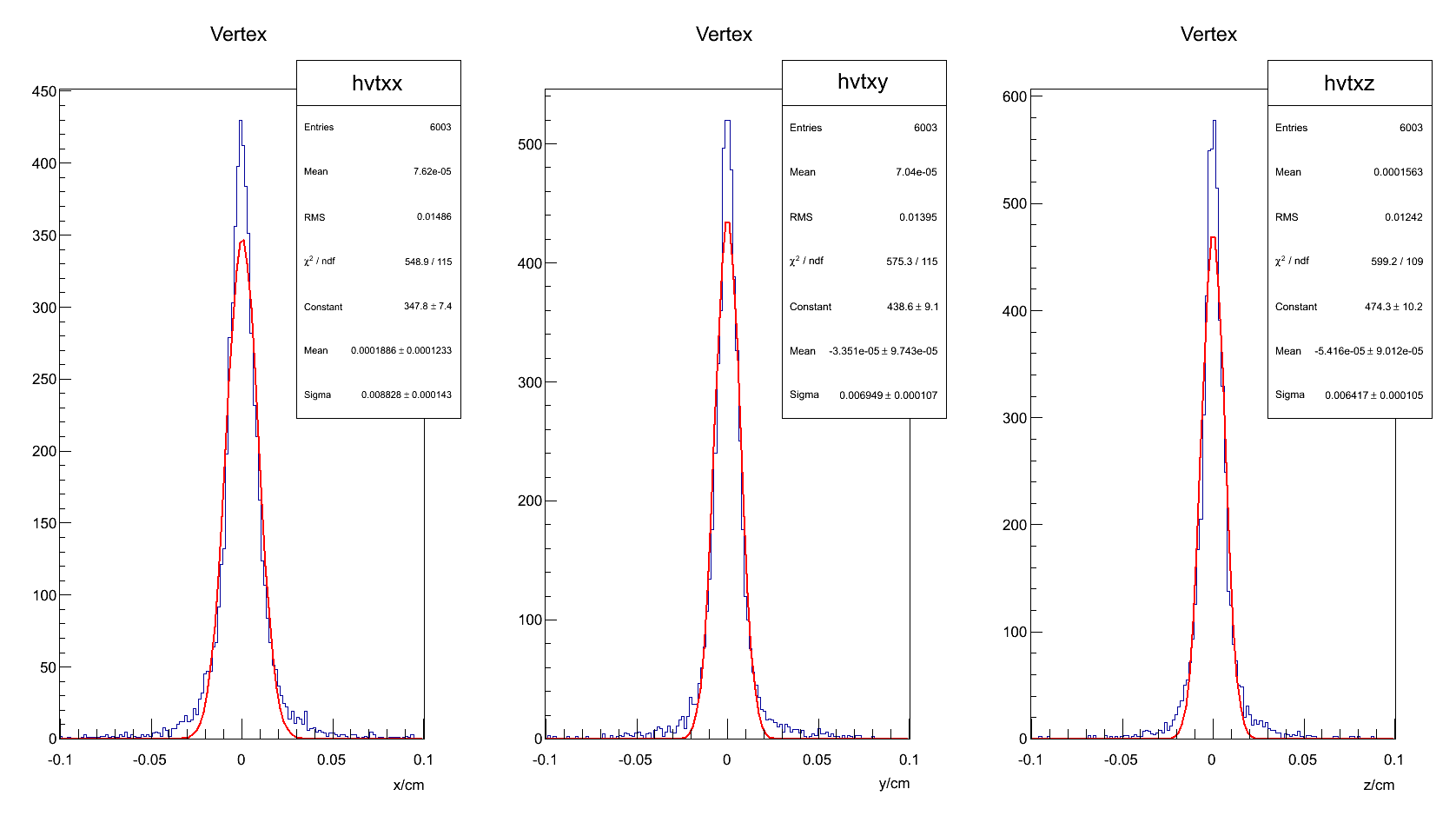
I fill histograms with the three components of the reconstructed vertices. As you can see in the attached figures I get a significantly different sigmas for x and y.

X always looks worse (even with different momenta and theta ranges).
I have already tried with different topologies like using two particles instead of four, or using pions of the same charge, but I always get worse results for X.
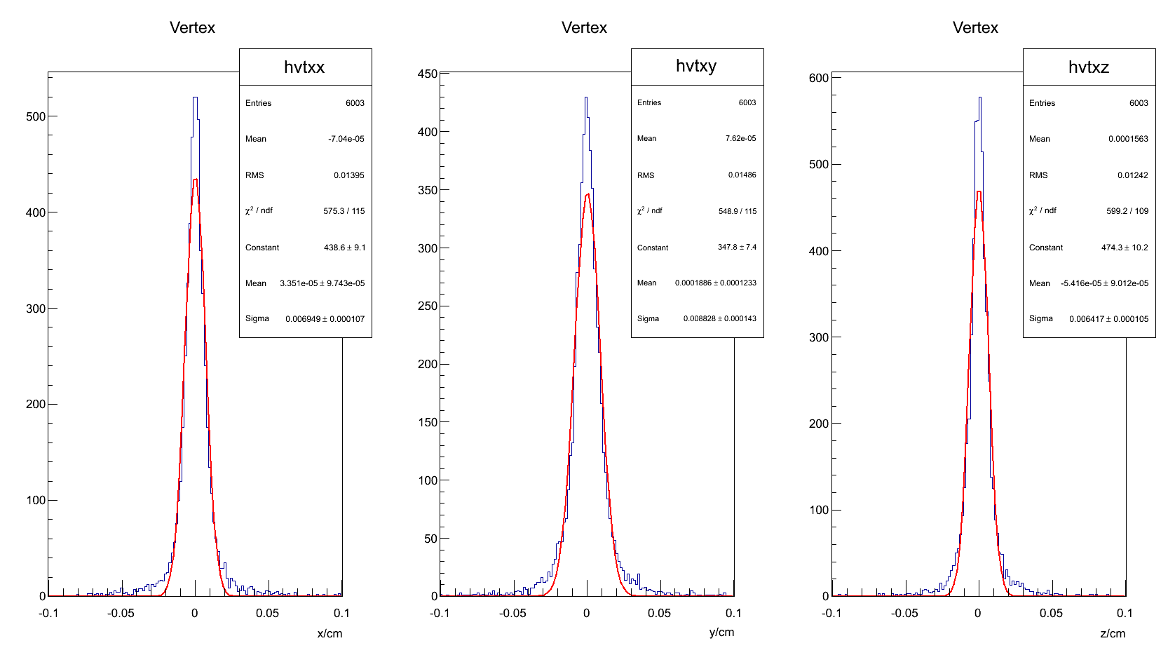
I tried with different vertexing tools (POCA, Ralf's fast fitter, another implementation of the POCA) and I always noticed this behaviour. It really seems to come from previous steps since if I try to rotate of 90° the tracks just before running the POCA vertex finder I obtain symmetrical results (worse Y than X, see the second figure attached).

Does any of you have an idea about possible reasons of this effect?
Thanks in advance.
Cheers,
Simone
|
|
|
|
|
|
|
|
|
|
|
|
|
|
| Re: Different x-y resolutions [message #12306 is a reply to message #12304] |
Wed, 20 July 2011 16:22   |
 Jens Sören Lange
Messages: 193
Registered: June 2005
|
first-grade participant |
From: *physik.uni-giessen.de
|
|
Hi Simone,
1.) my idea, that it could have something to do with the B field, came from the X and Y differences which were observed for luminosity monitor (which was to my knowledge the only time, that any azimuthal asymmetry was reported). Now I re-checked, and I found that I was wrong: it was not the dipole field generating the effect, but the aperture. See
http://forum.gsi.de/index.php?t=tree&goto=9206&rid=0&S=77db7 7666b257eeb980ffbd17eec1d35&srch=Jost#msg_9206
However, same as the dipole field, the effect should be forward peaked.
2.) HOWEVER, your result shows, that there is an effect even in your polar angle range.
After all, there might be an effect which was probably never seen before because you are looking at very small track DCA resolutions (50-60 um), but the B field grid is (if I remember correctly) in the central region 4 cm point-to-point distance (with linear interpolation between the points).
I checked field/PndMultiField.cxx
if (Map=="FULL") {

            PndTransMap *map_t= new PndTransMap("TransMap", "R");
                PndDipoleMap *map_d1= new PndDipoleMap("DipoleMap1", "R");
                PndDipoleMap *map_d2= new PndDipoleMap("DipoleMap2", "R");
                PndSolenoidMap *map_s1= new PndSolenoidMap("SolenoidMap1", "R");
                PndSolenoidMap *map_s2= new PndSolenoidMap("SolenoidMap2", "R");
                PndSolenoidMap *map_s3= new PndSolenoidMap("SolenoidMap3", "R");
                PndSolenoidMap *map_s4= new PndSolenoidMap("SolenoidMap4", "R");

                AddField(map_t);
                AddField(map_d1);
                AddField(map_d2);
                AddField(map_s1);
                AddField(map_s2);
                AddField(map_s3);
                AddField(map_s4);

        }else if (Map="DIPOLE") {
                PndDipoleMap *map_d1= new PndDipoleMap("DipoleMap1", "R");
                PndDipoleMap *map_d2= new PndDipoleMap("DipoleMap2", "R");

                AddField(map_d1);
                AddField(map_d2);

        }else if (Map=="SOLENOID") {

                PndSolenoidMap *map_s1= new PndSolenoidMap("SolenoidMap1", "R");
                PndSolenoidMap *map_s2= new PndSolenoidMap("SolenoidMap2", "R");
                PndSolenoidMap *map_s3= new PndSolenoidMap("SolenoidMap3", "R");
                PndSolenoidMap *map_s4= new PndSolenoidMap("SolenoidMap4", "R");

                AddField(map_s1);
                AddField(map_s2);
                AddField(map_s3);
                AddField(map_s4);
        }
so when you change from "FULL" to "SOLENOID", it means:
it is the SAME solenoid maps, but only the dipole map and the trans map IN ADDTION (!).
In the moment, I don't understand why you see such a strong effect for the dipole field. The best would be to switch off the B field completely, but then of course the track fitter does not work for straight tracks. I have the feeling that the track fitter also uses the field map, and then fails if B field in Geant and fitter are different. But I don't know where to set the field map for the fitter. I hope that someone else has a clever idea.
Soeren
|
|
|
|
|
|
|
|
|
|
|
|
|
|
|
|
Goto Forum:
Current Time: Sun Jul 13 18:36:08 CEST 2025
Total time taken to generate the page: 0.00665 seconds
|
 GSI Forum


