Home » PANDA » PandaRoot » Bugs, Fixes, Releases » Geometry Problems
| Geometry Problems [message #19230] |
Tue, 19 April 2016 14:47  |
 Stefan Pflueger
Messages: 99
Registered: February 2012
|
continuous participant |
From: *kph.uni-mainz.de
|
|
Hello everybody,
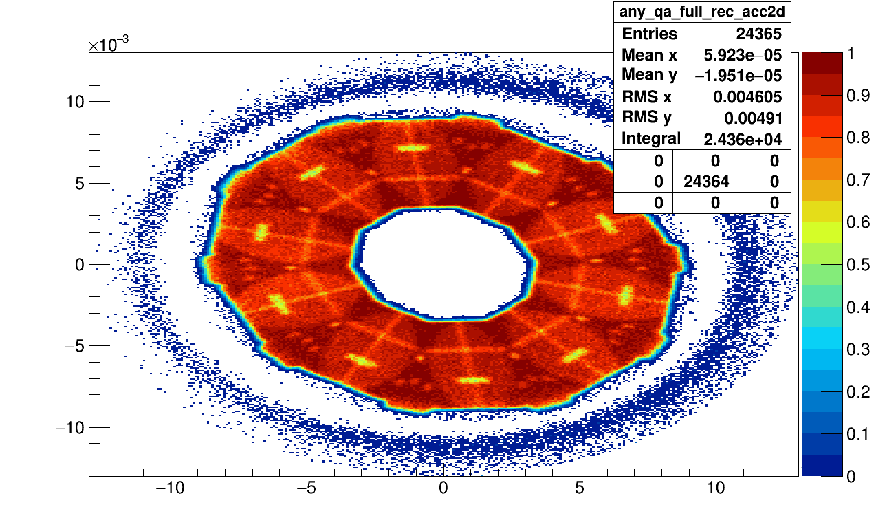
I wanted to inform you about a problem we have been dealing with the last week concerning our lumi detector geometry. Since this can also affect many other detector subsystems I wanted to share this with you. After an update of the fairroot (FairRoot-v-15.03) and external packages (mar15), we discovered that our 2 dimensional angular acceptance all of a sudden showed almond like shaped inefficiencies on the edges of our modules.

We analyzed the situation and came to the conclusion that this effect arises from the geometry not being constructed or simulated as we wanted.
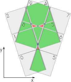
We have 10 modules aligned around the beampipe in circle. Each module consists of a diamond support and cooling structure having glued on 5 MuPix sensors on its front and 5 more on this back face.  The problem was that the diamond structure was constructed from a circle (or complete tube segment) and then being cut to the appropriate dimensions via a CompositeShape. The problem was that the diamond structure was constructed from a circle (or complete tube segment) and then being cut to the appropriate dimensions via a CompositeShape.
876	        // ****************************** cvd cooling support discs ************************
877	        // the cvd disc shape
878	        TGeoTube* shape_cvd_disc = new TGeoTube("shape_cvd_disc", 0.,
879	                        cvd_disc_rad, cvd_disc_thick_half);
880	        // The inner beam pipe defines the inner acceptance region for the cvd cut_out
881	        TGeoTube* shape_cvd_cutout_inner = new TGeoTube("shape_cvd_cutout_inner",
882	                        0., inner_rad, 1.);
883	        // finally cvd discs will be cut at the left and right down to 36 degree in phi
884	        // for that we subtract tube segments
885	        TGeoTubeSeg* shape_cvd_disc_cut_side = new TGeoTubeSeg(
886	                        "shape_cvd_disc_cut_side", 0., outer_rad, 1.,
887	                        +delta_phi / 2. / pi * 180.,
888	                        -delta_phi / 2. / pi * 180.);
889	        // before: cvd disc was moved to the displaced position around the z axis
890	        // now: segments for the cut are moved off centered and cvd disc remains in the center
891	        TGeoRotation* cvd_rotation = new TGeoRotation("cvd_rotation", 0, 0, 0);
892	        TGeoTranslation* cvd_translation = new TGeoTranslation("cvd_translation",
893	                        -cvd_disc_dist, 0, 0);
894	        TGeoCombiTrans* cvd_combtrans = new TGeoCombiTrans(*cvd_translation,
895	                        *cvd_rotation);
896	        cvd_combtrans->SetName("cvd_combtrans");
897	        cvd_combtrans->RegisterYourself();
898	        TGeoCompositeShape
899	        *shape_cvd_support =
900	                        new TGeoCompositeShape(
901	                                        "shape_cvd_support",
902	                                        "(shape_cvd_disc-shape_cvd_cutout_inner:cvd_combtrans-shape_cvd_disc_cut_side:cvd_combtrans)");
903
904	        TGeoVolume* lmd_vol_cvd_disc = new TGeoVolume("lmd_vol_cvd_disc",
905	                        shape_cvd_support, fgGeoMan->GetMedium("HYPdiamond"));
906	        lmd_vol_cvd_disc->SetLineColor(9);
The problem was that when we visually checked the geometry, everything seemed just fine. However in the simulation, the diamond was not cut off but the full circular shaped remained! Hence we observed a twice as high material budget on the edges of our modules that created this inefficiency in the acceptance.

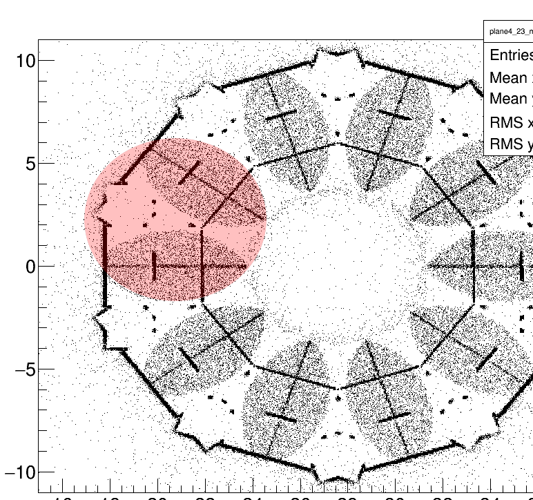
The red circle drawn into this picture would show where the diamond wafer would be sitting and its shows that it perfectly aligns with this almond like shape in the acceptance.
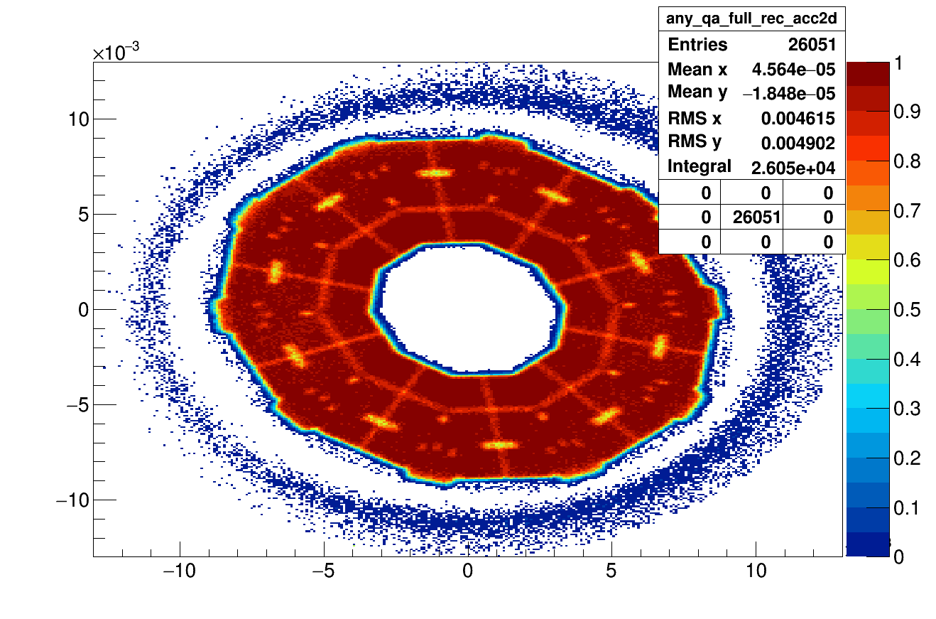
So simply changing this diamond shape to a tube segment with the correct phi and radii from the beginning on, prevented this overlap from appearing and the acceptance looked fine again.
// the cvd disc shape
886	        double gap_between_disc_and_support_structure(0.025); // 250 mu gap
887	        TGeoTubeSeg* shape_cvd_disc = new TGeoTubeSeg("shape_cvd_disc", inner_rad,
888	                        lmd_cool_sup_inner_rad - gap_between_disc_and_support_structure,
889	                        cvd_disc_thick_half, -delta_phi / 2. / pi * 180.,
890	                        +delta_phi / 2. / pi * 180.);
891
892	        TGeoRotation* cvd_rotation = new TGeoRotation("cvd_rotation", 0, 0, 0);
893	        TGeoTranslation* cvd_translation = new TGeoTranslation("cvd_translation",
894	                        -cvd_disc_dist, 0, 0);
895	        TGeoCombiTrans* cvd_combtrans = new TGeoCombiTrans(*cvd_translation,
896	                        *cvd_rotation);
897	        cvd_combtrans->SetName("cvd_combtrans");
898	        cvd_combtrans->RegisterYourself();
899
900	        //this next line is pretty stupid but it made the work for the better geometry minimal
901	        //otherwise I would have to do some deeper digging and reworking...
902	        TGeoCompositeShape *shape_cvd_support = new TGeoCompositeShape(
903	                        "shape_cvd_support",
904	                        "(shape_cvd_disc:cvd_combtrans+shape_cvd_disc:cvd_combtrans)");
905
906	        TGeoVolume* lmd_vol_cvd_disc = new TGeoVolume("lmd_vol_cvd_disc",
907	                        shape_cvd_support, fgGeoMan->GetMedium("HYPdiamond"));
908	        lmd_vol_cvd_disc->SetLineColor(9);

Either we are not using the composite shapes correctly in our code or ROOT seems to have a bug there.... Did anyone ever experience similar problems. I guess we were also lucky seeing this after all, as the material budget has to be just enough to actually slow down the particles enough so they are not seen in the last layers of the tracking detector anymore.
Best regards,
Stefan
-
 Attachment: acc2d.png
(Size: 72.87KB, Downloaded 1359 times)
-
 Attachment: circle.png
(Size: 77.86KB, Downloaded 1269 times)
-
 Attachment: sensor-overlap-new.png
(Size: 27.70KB, Downloaded 1298 times)
-
 Attachment: acc2d.png
(Size: 67.31KB, Downloaded 1237 times)
[Updated on: Tue, 19 April 2016 14:53] Report message to a moderator |
|
|
|
|
|
|
|
| Re: Geometry Problems [message #19235 is a reply to message #19234] |
Wed, 20 April 2016 14:08   |
 StefanoSpataro
Messages: 2736
Registered: June 2005
Location: Torino
|
first-grade participant |

From: *to.infn.it
|
|
StefanoSpataro wrote on 14 September 2015 16:42
Dear all,
after a long delay I put the QA macros inside macro/qa/lmd. I reduced the number of events to 1000 since it is too slow and in some computer it took more than 6 minutes for 2000.
In reality, I noticed that sometimes the sim macro is crashing and I have not understood why. In particular in my MAC I was not able to run the macros, it crash at event 0. When I am able to run, there are several geant4 errors from the geometry:
-------- WWWW ------- G4Exception-START -------- WWWW -------
*** G4Exception : GeomNav1002
issued by : G4PropagatorInField::ComputeStep()
Particle is stuck; it will be killed.
Zero progress for 51 attempted steps.
Proposed Step is 1.99896e-05 but Step Taken is 1.99896e-05
in volume lmd_vol_cvd_disc
*** This is just a warning message. ***
-------- WWWW -------- G4Exception-END --------- WWWW -------
-------- WWWW ------- G4Exception-START -------- WWWW -------
*** G4Exception : GeomNav1002
issued by : G4PropagatorInField::ComputeStep()
Particle is stuck; it will be killed.
Zero progress for 51 attempted steps.
Proposed Step is 1.74027e-05 but Step Taken is 1.74027e-05
in volume lmd_vol_vac
*** This is just a warning message. ***
Then maybe the geometry has internal problems. Doing a CheckFullGeometry I found the following:
====================================================================
STAGE 2: Global overlap/extrusion checking within 10 microns
====================================================================
Info in <TGeoNodeMatrix::CheckOverlaps>: Checking overlaps for cave and daughters within 0.001
Warning in <TGeoChecker::CheckOverlaps>: Volume lmd_vol_ref_sys with 2 daughters but not voxelized
Check overlaps: [==========] 1589 [100.00 %]
Info in <TGeoNodeMatrix::CheckOverlaps>: Number of illegal overlaps/extrusions : 12
and
====================================================================
STAGE 3: Propagating 1000000 tracks starting from vertex
and conting number of boundary crossings...
====================================================================
Error in trying to cross boundary of SupportCylinderov831_2 00:00:00
Error in trying to cross boundary of SupportCylinderov831_2 00:00:00
Error in trying to cross boundary of SupportCylinderov831_2 00:00:00
Error in trying to cross boundary of SupportCylinderov831_1 00:00:00
Error in trying to cross boundary of SupportCylinderov831_2 00:00:00
Error in trying to cross boundary of SupportCylinderov831_1 00:00:01
Error in trying to cross boundary of SupportCylinderov831_1 00:00:01
Error in trying to cross boundary of SupportCylinderov831_2
...
I don't know if you have ever seen such problems.
Moreover, I noticed that the reco macro in my Mac is failing, since it seems the trafo_matrices_lmd.dat path is hardcoded, and if you change the path of the macro then you have the crash. If it has to be used in the common framework this should become more general, i.e. parameters should be loaded inside some ParameterClass by the standard Ascii file.
To summarize, the lmd qa macros are on the dashboard, but they can fail and the output is not well stable.
Regards
Stefano
|
|
|
|
| Re: Geometry Problems [message #19236 is a reply to message #19233] |
Wed, 20 April 2016 15:39   |
 Stefan Pflueger
Messages: 99
Registered: February 2012
|
continuous participant |
From: *kph.uni-mainz.de
|
|
Hi,
thx! Ok that looks indeed like these problems could be connected. Crash means the whole simulation is aborted, right? If so I never experienced this in my simulations... The errors seem like they could be coming from the strange geometry we had before. lmd_vol_cvd_disc is exactly the volume that was troublesome... would be interesting to see if these messages disappear now. I did a CheckFullGeometry() now and the only bad things I got is these warnings:
Quote:
Warning in <TGeoChecker::CheckOverlaps>: Volume lmd_vol_vac with 9 daughters but not voxelized
Warning in <TGeoChecker::CheckOverlaps>: Volume lmd_vol_ref_sys with 2 daughters but not voxelized
Warning in <TGeoChecker::CheckOverlaps>: Volume lmd_vol_half with 4 daughters but not voxelized
Warning in <TGeoChecker::CheckOverlaps>: Volume lmd_vol_plane with 6 daughters but not voxelized
Warning in <TGeoChecker::CheckOverlaps>: Volume lmd_vol_module with 3 daughters but not voxelized
Warning in <TGeoChecker::CheckOverlaps>: Volume lmd_vol_side with 3 daughters but not voxelized
Warning in <TGeoChecker::CheckOverlaps>: Volume lmd_vol_die with 6 daughters but not voxelized
Warning in <TGeoChecker::CheckOverlaps>: Volume lmd_vol_die with 4 daughters but not voxelized
Warning in <TGeoChecker::CheckOverlaps>: Volume lmd_vol_side with 3 daughters but not voxelized
Warning in <TGeoChecker::CheckOverlaps>: Volume lmd_vol_die with 6 daughters but not voxelized
Warning in <TGeoChecker::CheckOverlaps>: Volume lmd_vol_die with 4 daughters but not voxelized
Im not sure how bad this is... what does the voxelized mean? At least the diamond support seems not to be part in it. Everything else looks clean. I just had a thought, maybe our mistake was setting the cut shape thicknesses to 1. in the old geometries. That is kind of unnecessary and could introduce some problems...
[Updated on: Wed, 20 April 2016 15:39] Report message to a moderator |
|
|
|
| Re: Geometry Problems [message #19247 is a reply to message #19236] |
Thu, 28 April 2016 13:58   |
 StefanoSpataro
Messages: 2736
Registered: June 2005
Location: Torino
|
first-grade participant |

From: *to.infn.it
|
|
When you have a volume with daughters, the modeler creates for each volume some optimization structures called voxels (see Voxelization) to minimize the penalty having too many daughters in your tracking performance. I.e. in a structure where you have many daughters, such as a pixel layer, or a chambers with thousands of wires, to find in which volume the point (x,y,z) is located (you have to imagine a loop into all the daughter volumes).
If I remember correctly, the warning appears when the bounding box of an assembly is smaller than the inside volumes. In any case, the warning reflects some anomaly in the geometry, virtual or non virtual overlaps of clashes. Have you tried to take a look into such volumes, to understand what could be the possible reason? Which lmd geometry are you checking?
|
|
|
|
|
|
|
|
Goto Forum:
Current Time: Tue Jan 27 15:14:23 CET 2026
Total time taken to generate the page: 0.01159 seconds
|
 GSI Forum


